Why Do weather compensation curves matter?
Because almost all commercial buildings that use radiators or underfloor heating, have weather compensation. Not only that, but all the top boiler manufacturers are installing the provision into the domestic sizes as well!
Weather compensation may seem like an advanced concept, but it is surprisingly straightforward when broken down. By programming the “funny-looking” graphs on boiler room controllers, you can impress both your boss and customers with your technical expertise. These graphs are essential for most wet heating systems with radiators or underfloor heating, and understanding how they work brings significant benefits:.
Know Your System: With numerous control system variations available, understanding your setup is crucial.
Assess System Performance: Routine checks ensure the system is functioning optimally, with the ability to override manually if necessary.
Specify and Commission: Wiring, actuators, and sensors require knowledge to configure and maintain weather compensation successfully.
Simplifying Weather Compensation: Start with the Basics

Weather Compensation Looks Tricky but Can Be Simplified
Weather compensation is more accessible than it appears. By focusing on just three critical points on a graph, you can configure the system efficiently. These points determine when the heating operates at full capacity, medium output, and when it shuts off entirely.
Graph Basics: The graph’s key points are simple. Decide the outdoor temperature for full heating, half capacity, and shut-off. For example, at 5°C, heating should run at full power, while at 20°C, it should turn off completely.
Full Output Settings: Set the flow temperature for maximum heating at around -5- 0°C outdoor air temperature (OAT). If you want to drive effeciency, but if want comfort then you can go as high as 5°C.This is your system’s baseline for cold weather operation.
Medium and Shut-off Points: Medium output settings are typically between 10°C and 12°C, providing balanced heating. At 20°C OAT, the system should shut off entirely, saving energy.
The annoying maths bit. You can programme a weather comp curve in a couple of different ways. The more complex way is to learn the y=mx+c formula off by heart and then work out the gradient and c.
By learning these concepts and using the math to work it out before making the changes to the plant. Engineers can simplify setup and ensure efficient system operation.
One of best things to do is, try and work out the flow set point from the parameters that you can set. Make the changes and then observe what happens.
Recognizing VT Circuit Control Types
Three Common VT Circuit Controls You’ll Encounter
Understanding the control systems behind variable temperature (VT) circuits is vital for effective maintenance and programming. Whether dealing with a building management system (BMS) or parameter-based controls, a clear methodology will ensure smooth operation.
- BMS-Based Controls: These systems offer extensive customizability. Controllers like those found in high-end setups but are only open engineers who are able to access the internal programming. A lot of the time these can be remote monitored so you might need to call someone to override or check the parameters. Sometimes I have had to resort to physically disconnecting the Actuator from off the VT valve in order to override the heating system. You just have to make sure to read the manual of the Actuator because the wrong screw can loosen the Actuator spindle and spray hot water all over your face! (Big tip, don’t leave an actuator head off, it will really annoy your controls guy)
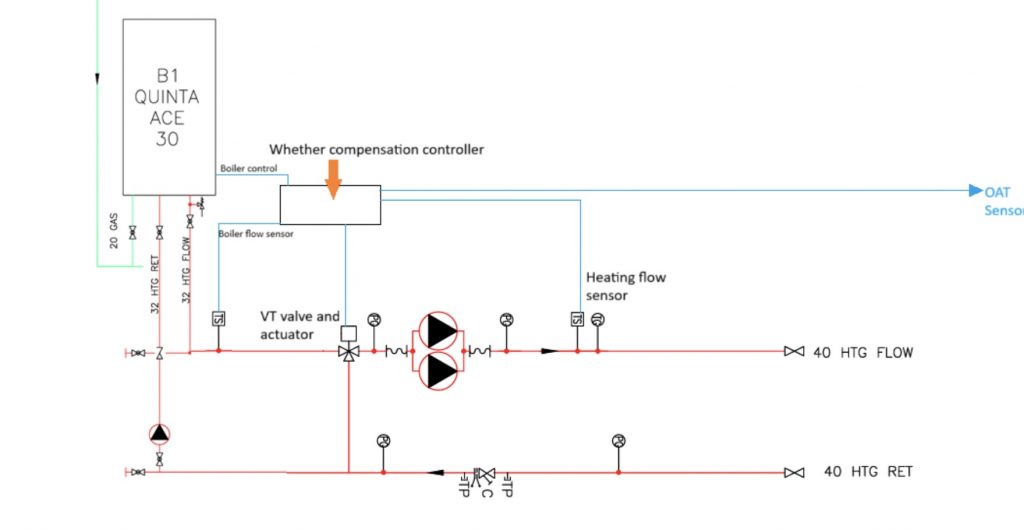
- Preprogrammed Controls: These typically feature floating-point valves and preset parameters, making them simpler but less flexible. For example, the Series 90C Weather Compensating Controller provides an efficient solution for such setup utilising a boiler based control system. These are preprogrammed controllers. Most of the boiler manufacturers make thier own that intergrate directly into thier boilers.
- A lot modern boilers come with the ability to have an OAT sensor wired directly into its own PCB, simplify control within a single system. Boilers like the Strebel SCB80 have manuals that detail these configurations, making it easier to set up the controls effectively. These are generally single boiler systems, but some can be easily cascaded together. Again the Strebel SCB range has the ability to do this as standard. Valliants and Pottertond require extra PCBs.
I have included a link to a wheather compensation controls that works from parameters below:
https://www.siemens-landis-supplier.co.uk/download/MANUALERVL479-RVL480.pdf
Methodically identifying and working with these control types using checklists ensures proper system setup and operation.
Wiring VT Circuits: Demystifying Installation
Wiring VT Circuits with Three Common Approaches
Wiring VT circuits can be daunting, but understanding the three main approaches simplifies the task. Whether integrating with BMS, variable temperature valve controls, or modern boilers, knowing the wiring methods ensures reliable performance.
BMS Integration: BMS wiring can be complex unless you’re familiar with these systems. Generally you are going to need to have a a set of panel drawings because the freely programmable controllers can be set up in any infinte number of ways.
Preprogrammed controllers will almost always use a VT mixer valves unless they have a serial link with the boiler (This is becoming more common), but it really does depend on set up. For example the Seimens controller I provided a link for, will just have a relay output for each boiler you have and two relay outputs for the valve ( one to open and one to close the valve). You will also get a realy output for the heating pumps and hotwater.
Variable Temperature Valve Controls: Controllers like Siemens make wiring these systems straightforward. Manuals provide clear instructions to streamline installation.
Onboard Boiler Controls: Modern boilers often combine OAT sensors with onboard controls, simplifying wiring tasks. Whether dealing with old sequences or cascaded setups, knowing the sensor ports is critical.
Conclusion: Unlocking the Full Potential of VT Circuits
Weather compensation is a powerful tool that can seem overwhelming at first glance, but with a systematic approach, it becomes manageable.
From understanding graph points to identifying control types and mastering wiring, these steps are essential for maintaining efficiency in commercial heating systems. By implementing a checklist-driven process, engineers can:
- Confidently program weather compensation graphs.
- Assess and override systems during service visits.
- Specify, commission, and wire systems effectively.
Ready to Save Energy?
If you want to learn more about your commercial heating plant, then please get in contact using my contact page. If your domestic engineer and want to show that you can play with the big toys then subscribe because I am going to be sharing my knowledge through posts and videos.
Pingback: #renewables #energy efficiency #solar #heat pumps